Problem Statement
The goal: carry a backpack on the side of a bicycle, leaving the top of the existing rack clear for other cargo.
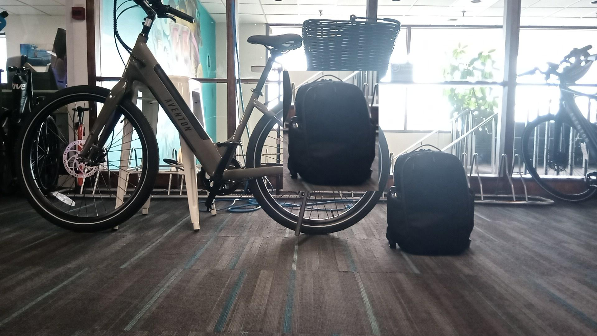
// Side profile showing the target placement of the backpack relative to the existing rack/basket.
Two constraints shaped the entire design. First, the existing rack has a round tube running across its top — any attachment point needed to account for that geometry. Second, the backpack has a luggage-handle strap — a hook built into the main body could hold the backpack without needing to modify the backpack.
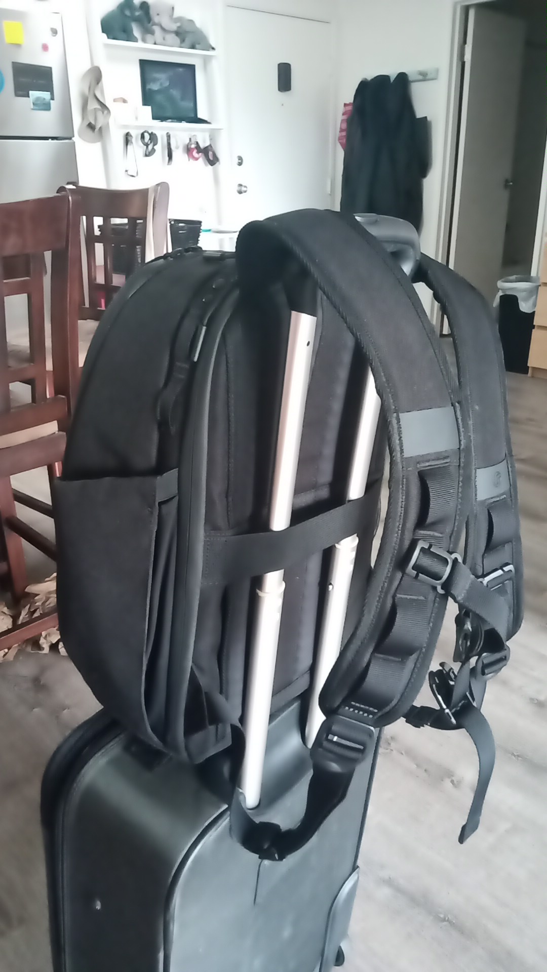
// The luggage-handle strap that became the attachment interface.
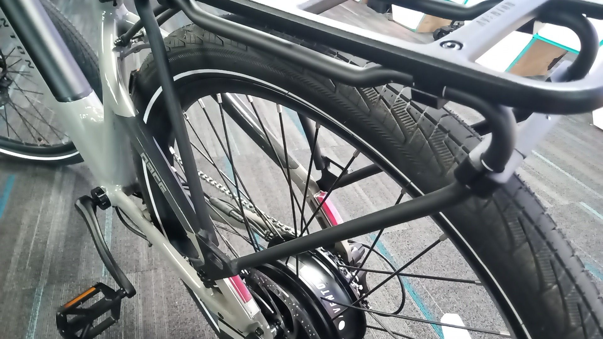
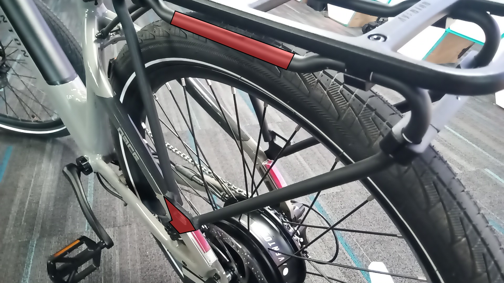
// Drag to compare: red highlights indicate the round top tube (upper) and flat mounting junction (lower) — the two geometric constraints that drove the entire design.
Reverse Engineering
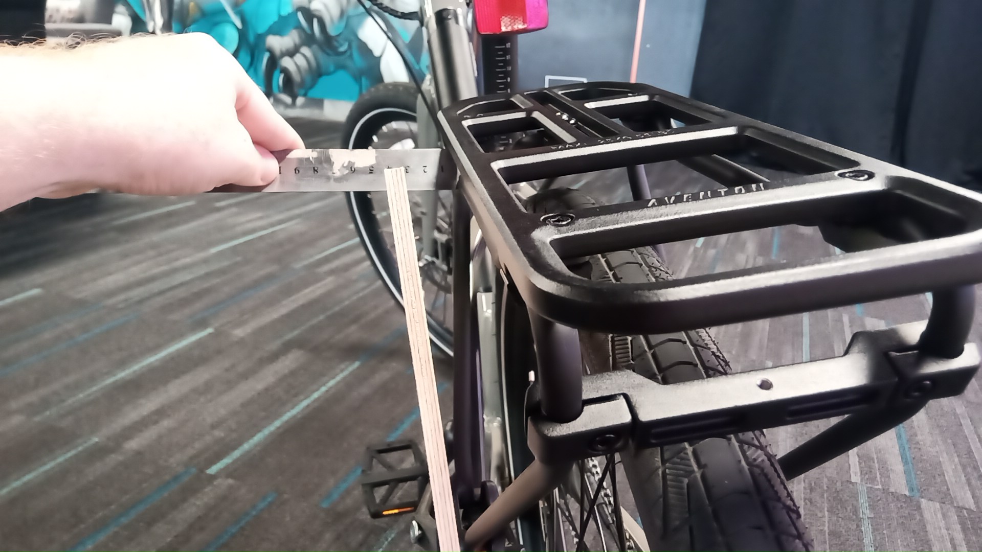
Before I could draw the first revision in CAD, I needed to know the existing geometry of the bike and rack as currently installed, relative to each other. A driving feature of the existing rack was a flat surface that could accommodate a bolt. Planning to use that to bolt my new design to, and using a bar across the top to hang most of the weight on (see above), I fabricated a simple plate for taking accurate measurements.
These numbers could be recreated in CAD, and the first revision drawn around them.
Design & Iteration
Revision 1 — Concept Locked
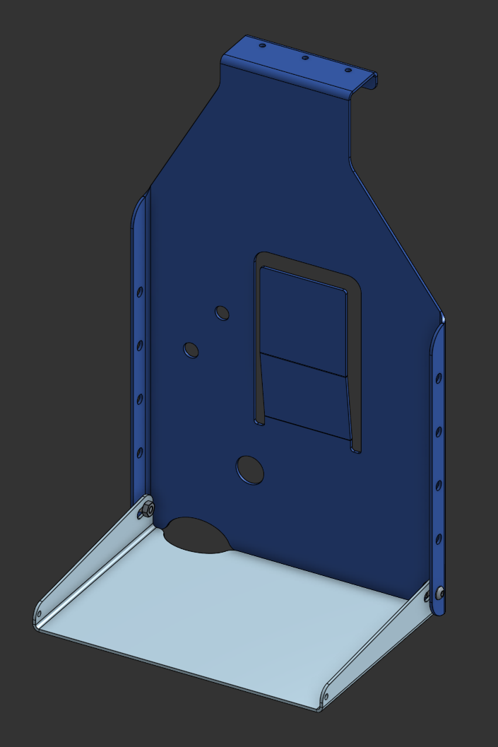
The Rev 1 design established the core architecture: a single-piece sheet metal backplate with a hook at the top to engage the bike's round tube, bolt holes at the base to tie into the existing rack, a luggage-strap finger to grip the backpack, and a folding shelf hinged at the bottom for weight support.
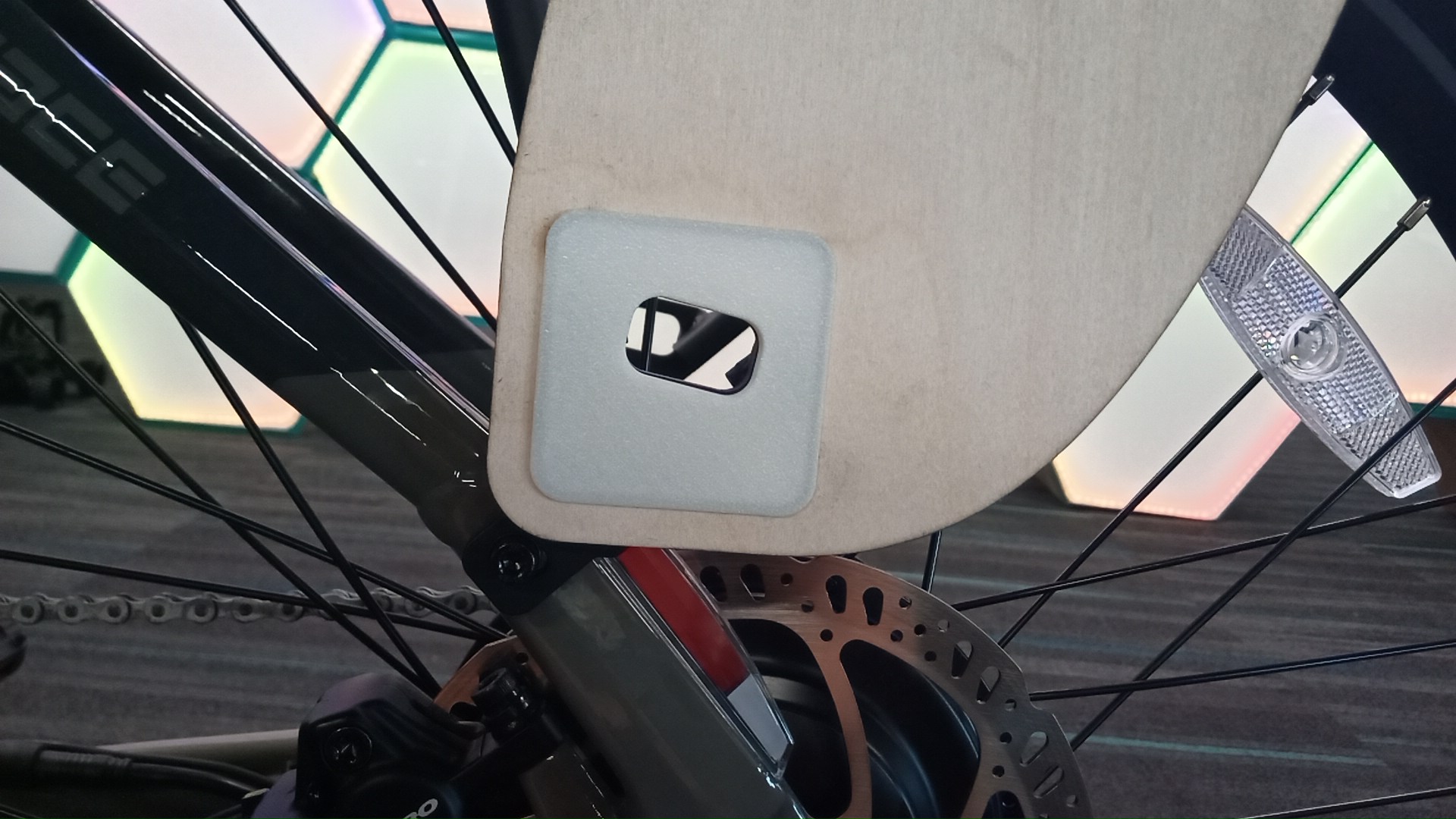
The fold-up shelf allows the rack to pack flat when not in use, and rests in the down position under load via a simple bolt-and-slot locking mechanism.
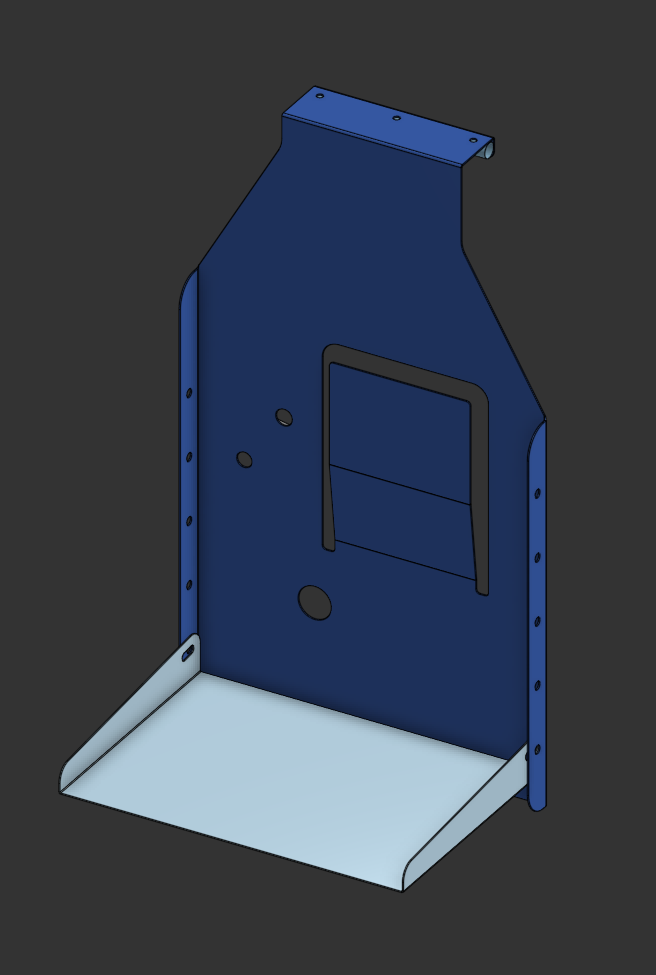
// Rev 1 CAD. Hole pattern, hook geometry, and shelf hinge all defined at this stage.
Plywood Prototype — Fit Check Before Committing to Metal
Rather than order sheet metal and discover a fit problem after the fact, the Rev 1 design was first laser-cut in plywood — cheap, fast, and perfectly adequate for a dimensional check. The prototype was assembled on the bike to verify mounting geometry and shelf position before any sheet metal was ordered.
Process Note: Laser-cutting a plywood prototype costs a fraction of a sheet metal run and can catch geometry errors in minutes. This step compressed the revision cycle significantly.
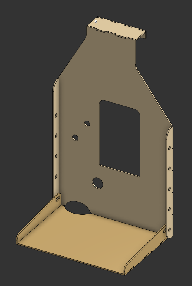
// Render of plywood model. All pieces were cut out of flat stock and glued together to a 3D shape.
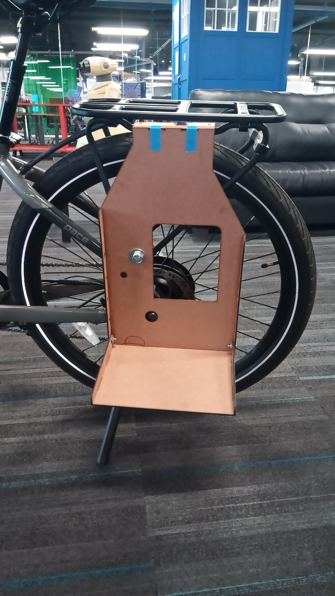
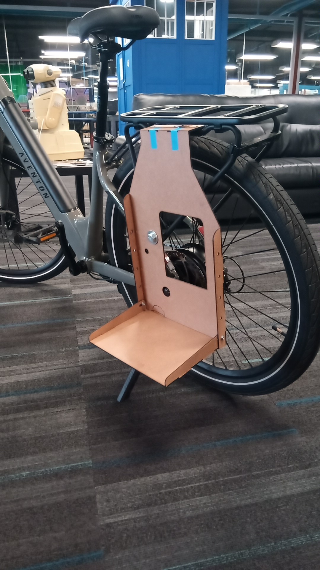
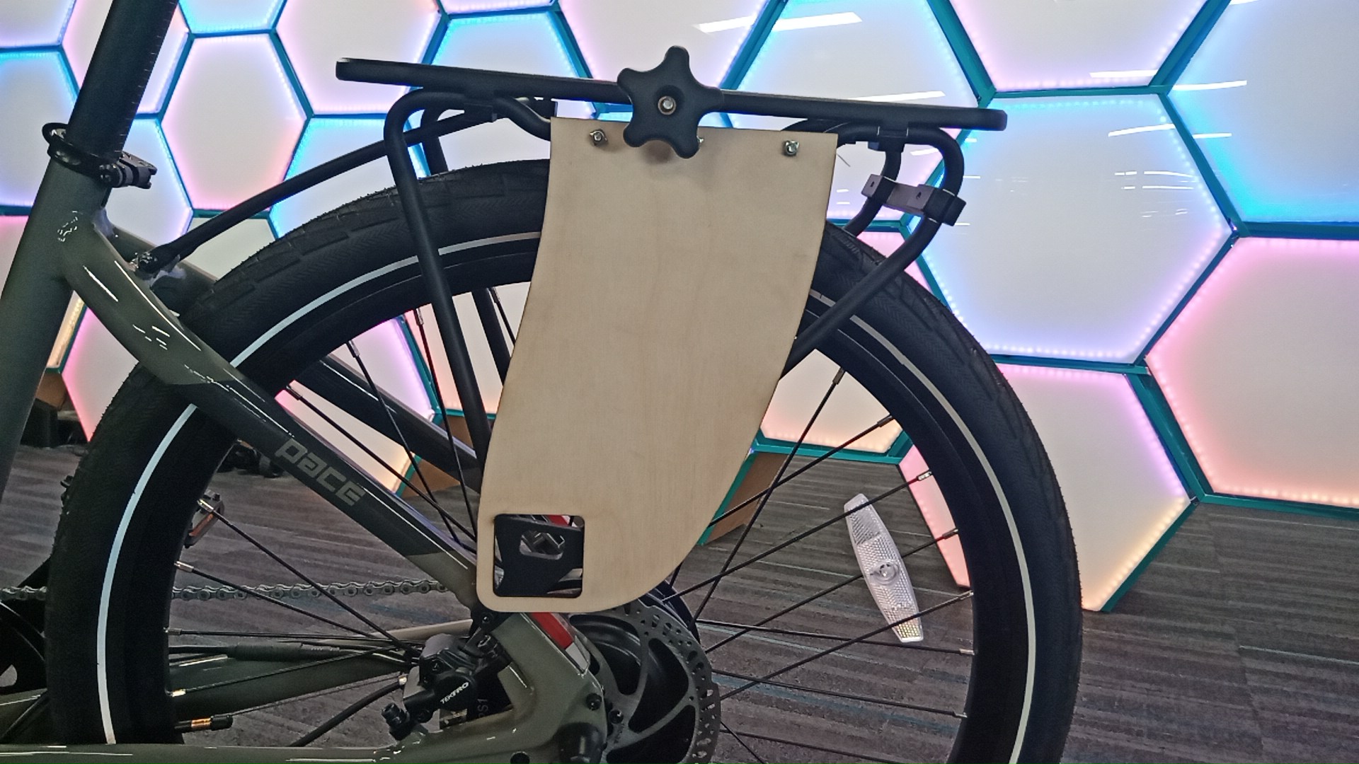
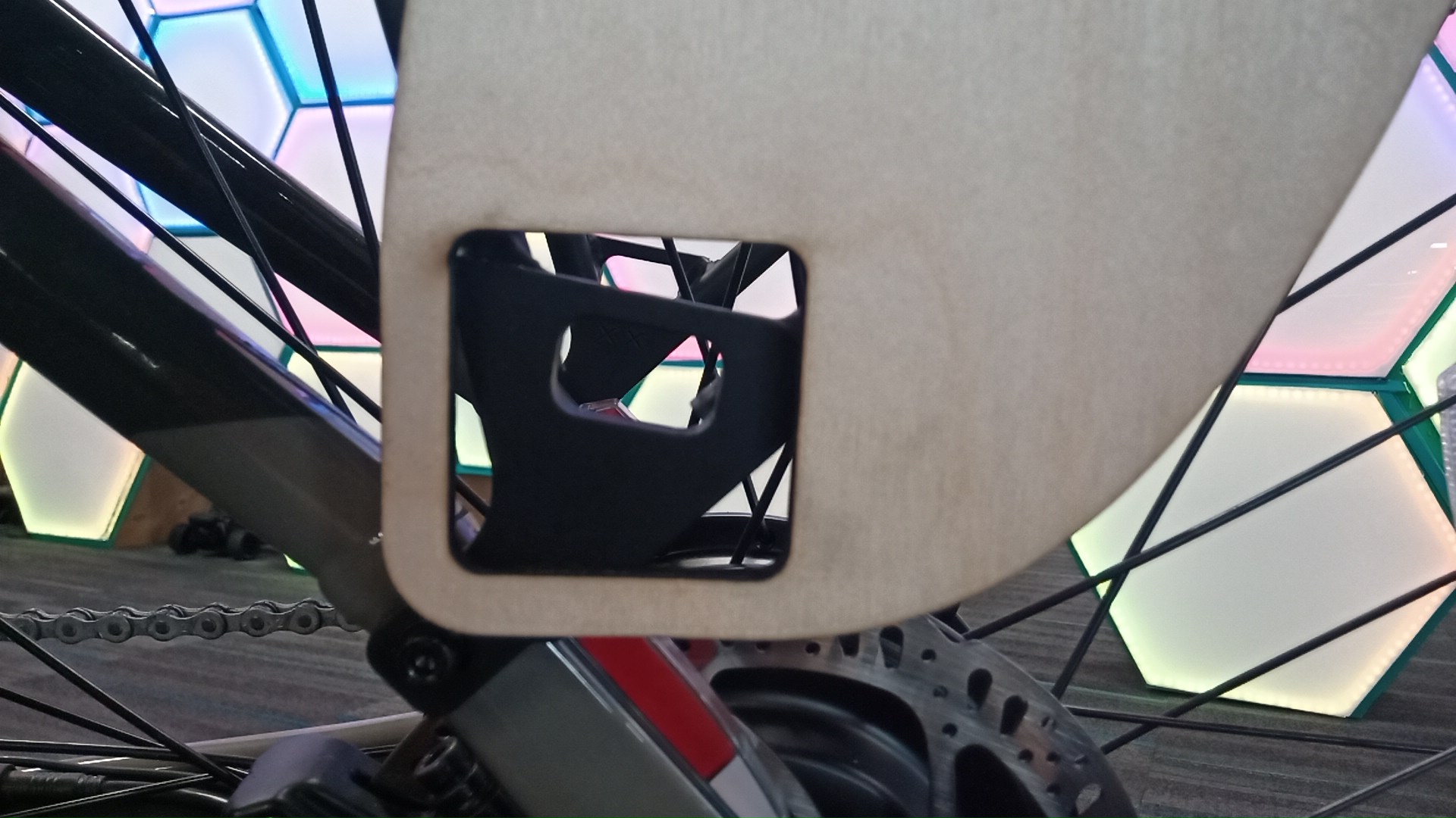
// Plywood prototype fitted to the bike. Folding shelf extended, hardware cutout and locking bolt visible. Blue tape holds the hook to the top tube during the fit check. Geometry confirmed; minor adjustments fed into Rev 2.
Revision 2 — Final Design for Manufacture
Lessons from the plywood prototype fed into Rev 2: minor adjustments to the hook radius, shelf bracket angle, and bolt clearances. Material and thickness were also finalized at this stage — the design was optimized for the specific bend radii of SendCutSend's press brake process.
// Rev 2 CAD — final geometry submitted for manufacture.
Manufacture & Assembly
Parts were ordered through SendCutSend. Turnaround from file submission to parts in hand was under one week.
| Fabrication Method | Laser cut + CNC press brake |
| Supplier | SendCutSend |
| File Format | STEP |
| Hardware | Stainless bolts, locking nut, spacer |
| Finish | Custom spray paint (stencil-applied) |
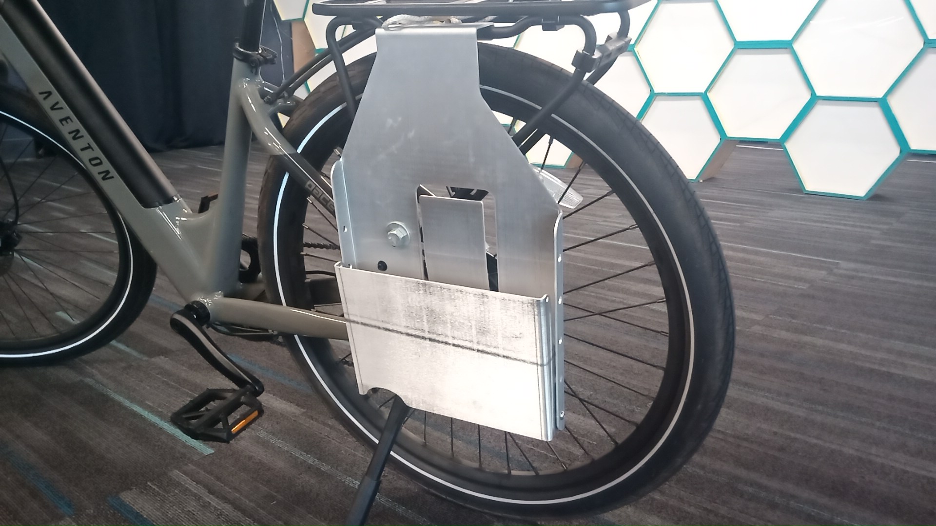
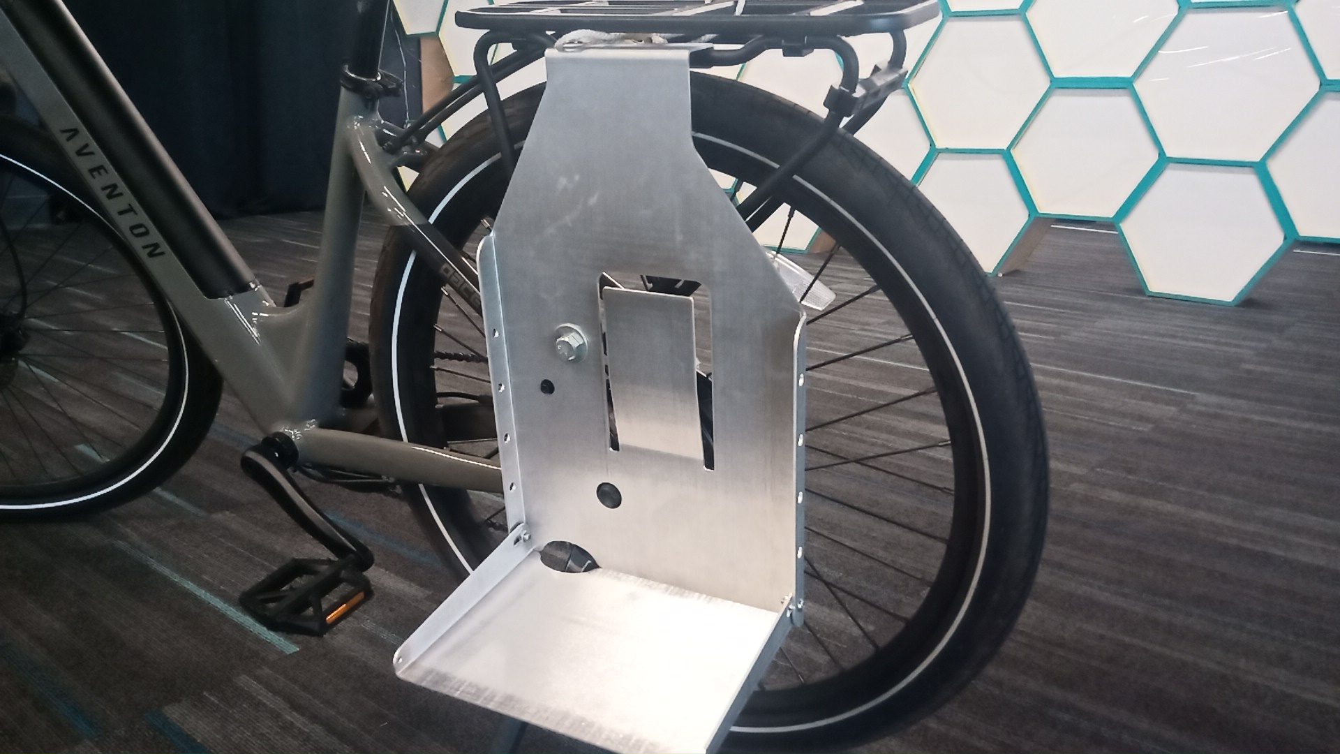
// Parts as-received from SendCutSend. Drag to compare shelf positions — folded down for use, folded up when not needed.
Finishing — Custom Paint
The final step was purely cosmetic but worth it: a custom logo stencil was laser-cut from scrap acrylic and used to spray-paint a graphic of my own design onto the finished rack.
// Laser-cut acrylic stencil. The negative space becomes the painted mark.
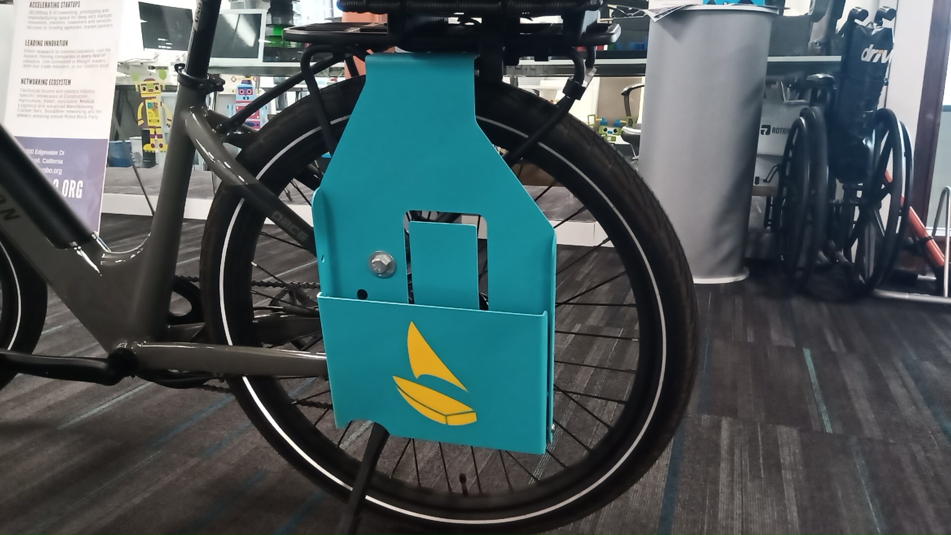
// Finished rack
Skills Demonstrated
Process Summary
Constraints & Measurements
Reverse-engineered existing rack geometry; identified mounting surfaces and constraints.
CAD — Rev 1
Full sheet metal model in OnShape. Folding shelf, hook, strap slot, and bolt pattern defined.
Plywood Prototype
Laser-cut in plywood for a low-cost, fast dimensional fit check on the actual bike.
CAD — Rev 2
Incorporated prototype findings. Geometry and material finalized for manufacture.
Sheet Metal Order — SendCutSend
DXF flat pattern and bend annotations submitted. Parts delivered in under one week.
Assembly & Finishing
Hardware assembled, custom stencil logo spray-painted. Installed and field-tested.