Not every project ends with a finished product. Some of the most valuable engineering work is methodical experimentation — running controlled tests, documenting what fails, and building reusable tools for future decisions. The three entries below document that kind of work.
01 —Designing for Watertightness
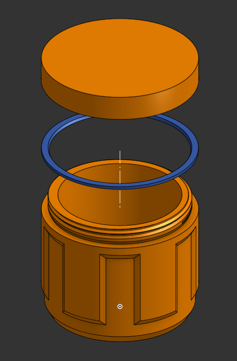
The question: can a 3D-printed enclosure reliably protect its contents in a wet environment? A custom container was designed with a screw-on cap and a custom TPU gasket, then subjected to progressively demanding experiments.
The honest answer turned out to be: it depends — and the experiment defined exactly where that boundary lies.
Note: This experiment did not fully succeed. It is documented here because a disciplined failure with clear conclusions and a defined next step is more useful than an undocumented one.
Experiment 1 — Basic Watertightness
1
Fill cup with water. Leave open in a large bowl overnight.
2
Check bowl for leaks or puddles.
Results
PLAUnreliable — leaks
PETGHolds water (good print required)
Experiment 2 — Pressurised Submersion
1
Enclose a paper napkin in the sealed container.
2
Submerge in a bucket of water; weigh down to prevent floating.
3
After a period of time, open and check napkin for moisture.
Results
PETG + TPU gasketFailed — napkin was wet
Conclusion & Next Step
PETG can resist passive liquid contact, but a custom TPU gasket is insufficient for pressurised submersion. The clearest next step: replace the custom gasket with a standard o-ring and design a matching groove into the CAD — a cheaper, more reliable, and more manufacturable solution.
CAD (OnShape)FDM 3D PrintingPETG / TPUExperimental MethodGasket DesignTechnical Drawing
When embedding magnets in a 3D-printed enclosure to hold a lid, a fundamental question arises before any design work can begin: how far apart should the opposing magnets be? Too close and the print wall is too thin to retain them; too far and the pull force is too weak. The answer varies by magnet size, printer calibration, and intended application — and must be measured, not assumed.
Rather than printing a series of complete enclosures with different spacings, a single compact test piece was designed that packs multiple spacing configurations into one print, exploiting the geometry of the part to test both sides of each sample simultaneously.
Now that I've gone through the work of making this, I can keep it forever and refer back to it any time I want to incorporate magnets as a retaining mechanism in my design, making an informed, intuitive decision on a case-by-case basis.
The Simple Case
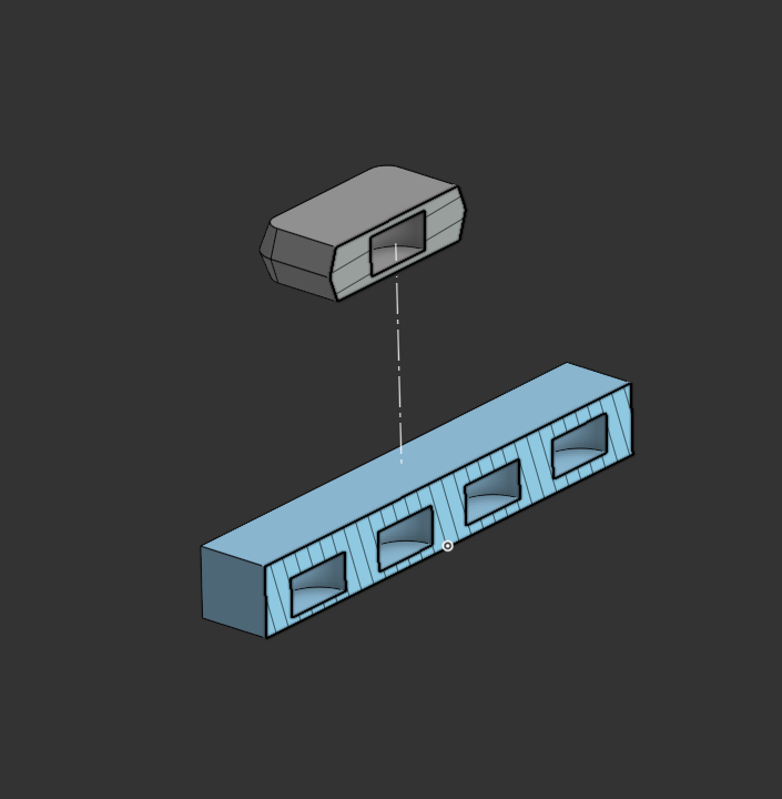
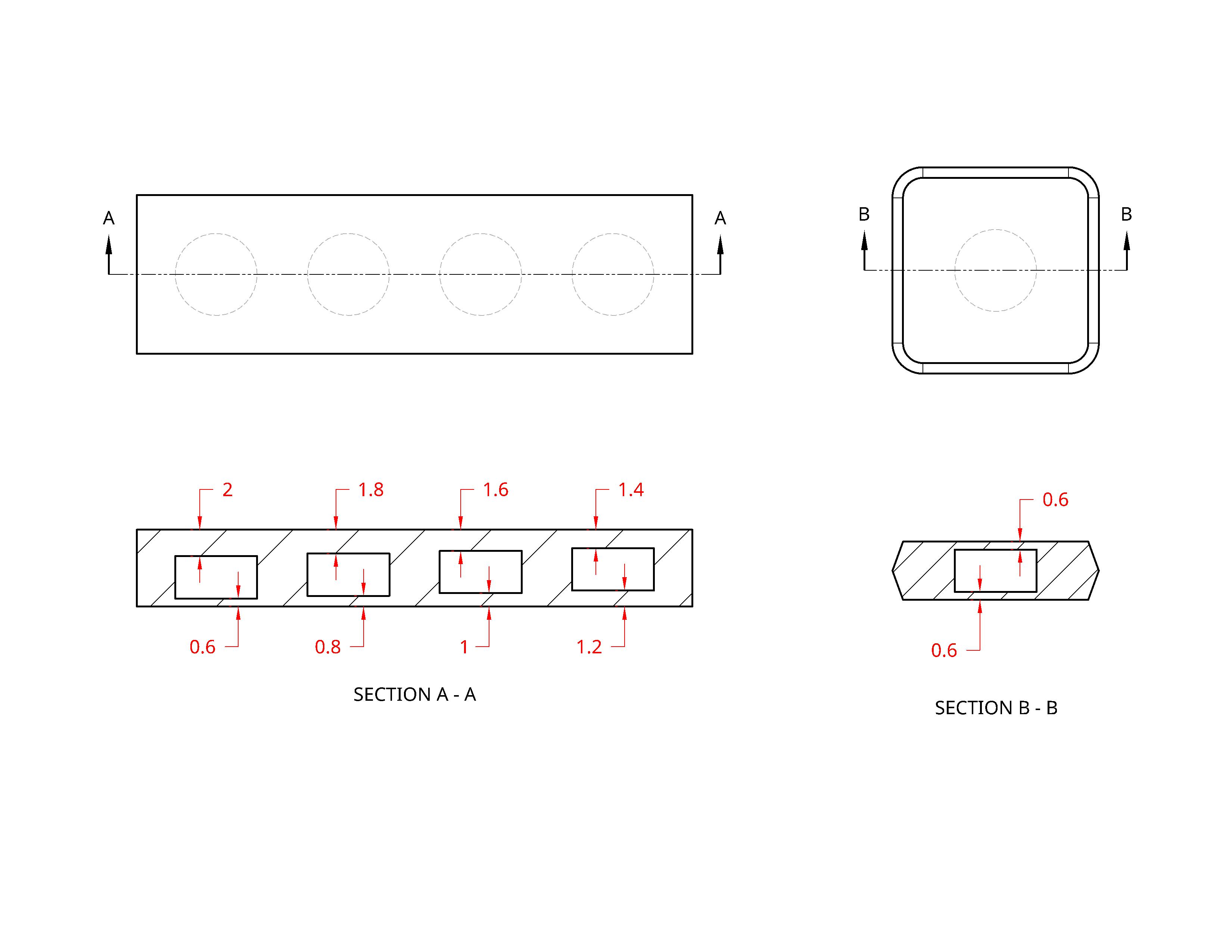
A rectangular block with four magnet cavities at different surface-to-surface spacings (0.6, 0.8, 1.0, and 1.2mm) pairs with a flat companion piece at a fixed 0.6mm. Flipping the companion piece over doubles the test range to eight configurations (up to 2.0mm) — all from one pair of prints.
// Four spacing configurations in one block; reversible to double the test range.
// Annotated CAD diagram showing the surface-to-surface spacing values for each cavity.
The Sophisticated Case
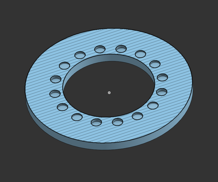
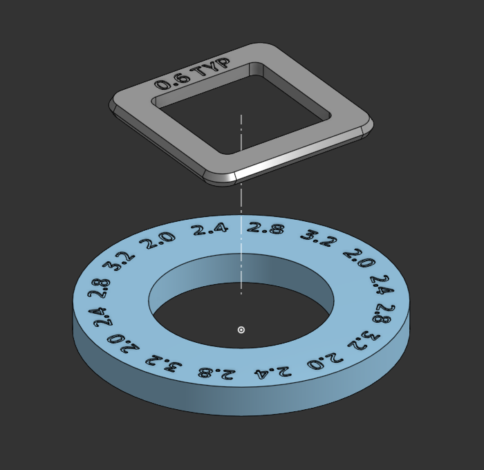
For a box with magnets at all four corners, a single-magnet test understates the total pull force by a factor of four. The solution: arrange four magnets per spacing group, in a square, repeated radially — producing 16 cavities in a cylindrical test piece, each group simulating the full corner arrangement of the final design.
// Sectioned model — 16 cavities in four radially symmetric groups of four.
// Companion square piece — each hole labelled in CAD to prevent assembly errors.
Design Note: Labeling each hole in the CAD model is tedious, but it is the only reliable way to maintain orientation during printing and assembly — the polarity of each magnet must be consistent or the test is invalid.
CAD (OnShape)FDM 3D PrintingExperimental DesignMagnet RetentionTolerance EngineeringSTEP Published
03 —A Study in Workholding
Workholding is the underappreciated foundation of precision CNC work: how you hold the part determines what accuracy is achievable. This project — machining a simple aluminium square on a Carvera desktop CNC — was chosen specifically to force a rigorous workholding solution, since a machinist square demands that all edges be straight and perfectly perpendicular to each other.
The Core Insight: To guarantee the outer perimeter of a part is cut precisely, all four edges must be cut in a single continuous path during one setup. The only way to achieve that is to clamp from the inside — which requires fixture holes to be bored before the final contour is cut.
The Goal
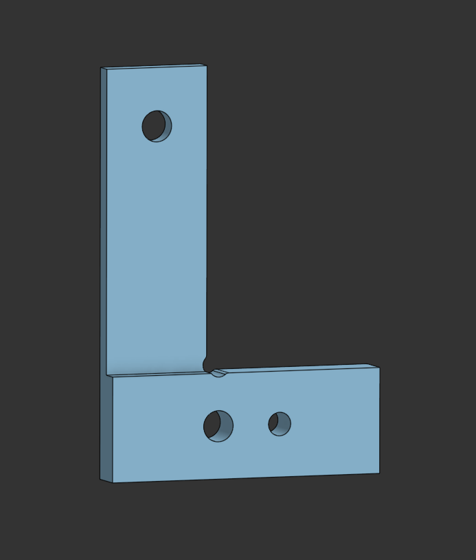
// Target part: a machinist square, as precise as the machine can cut.
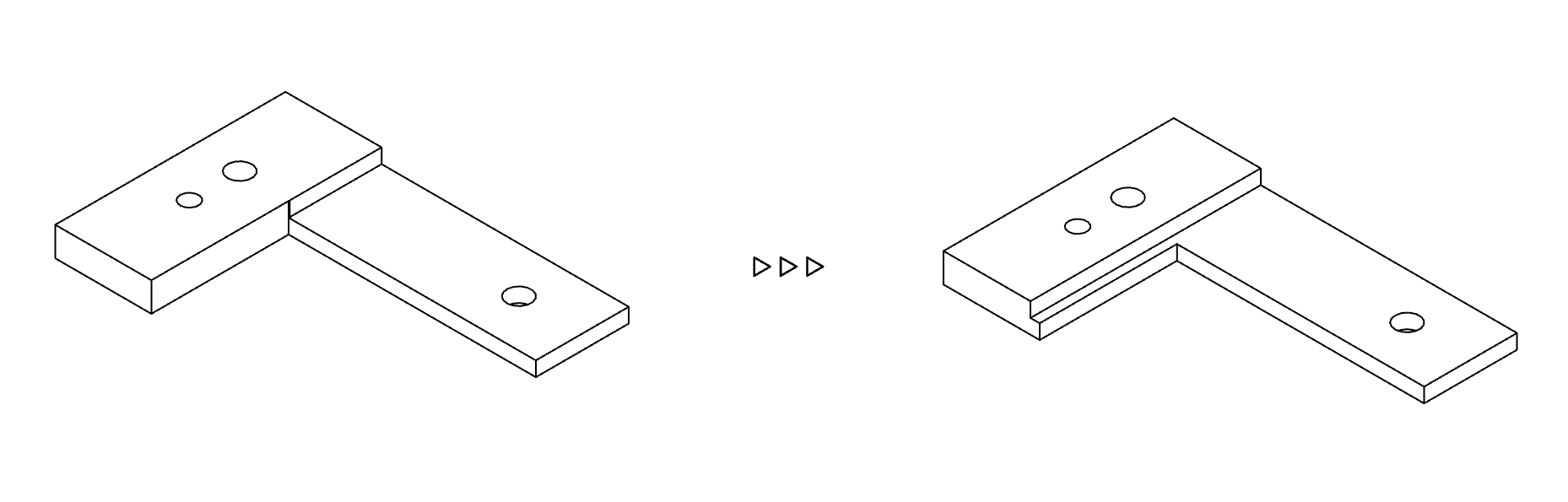
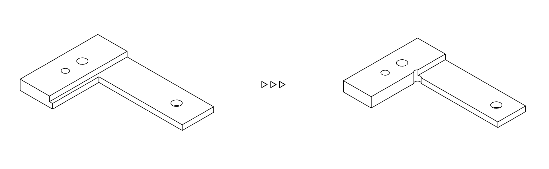
Inside Corners — Dogbone Cuts
Rotating cutters cannot produce sharp inside corners. The standard solution is an overcut: a small circular relief at each interior corner that allows a mating square part to seat correctly without interference.
// Dogbone overcut geometry — the inside corner is not sharp, but still accepts a square mating part.
Fixturing Strategy
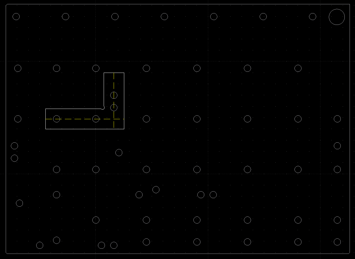
Mounting holes were designed into the part to align with the Carvera's known bed hole pattern, allowing the part to be bolted down from within after the first setup.
// Fixture holes added to the part model, strategically positioned to align with the machine bed.
// Part (white) superimposed over the Carvera bed fixture holes (grey) to confirm alignment.
Two-Setup Machining Plan
Setup 1 — Clamped on Outside Edge
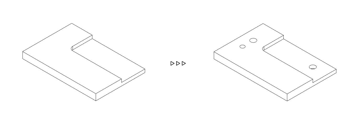
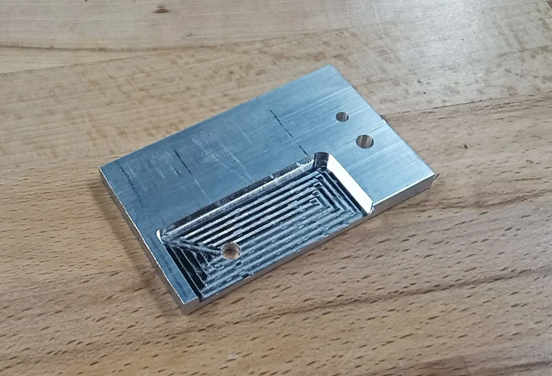
Op 1: Mill the interior pocket, starting oversized to account for rough factory edges on the stock. Op 2: Bore the fixture holes. Without matching drill bits for the machine's collet, holes are milled out — slower but effective for this diameter.
// Op 2: fixture holes bored, ready for second setup.
// Left: Op 1 — pocket milled with outside clamps. Right: part after Setup 1, pocket and fixture holes complete.
Op 3: Bandsaw the rough outer perimeter down close to final size — saving end mill time and cost on material that would otherwise be cut away slowly.
// Bandsaw trim — a conventional tool used deliberately to save CNC time. The sped-up video in the source document shows this operation in real time.
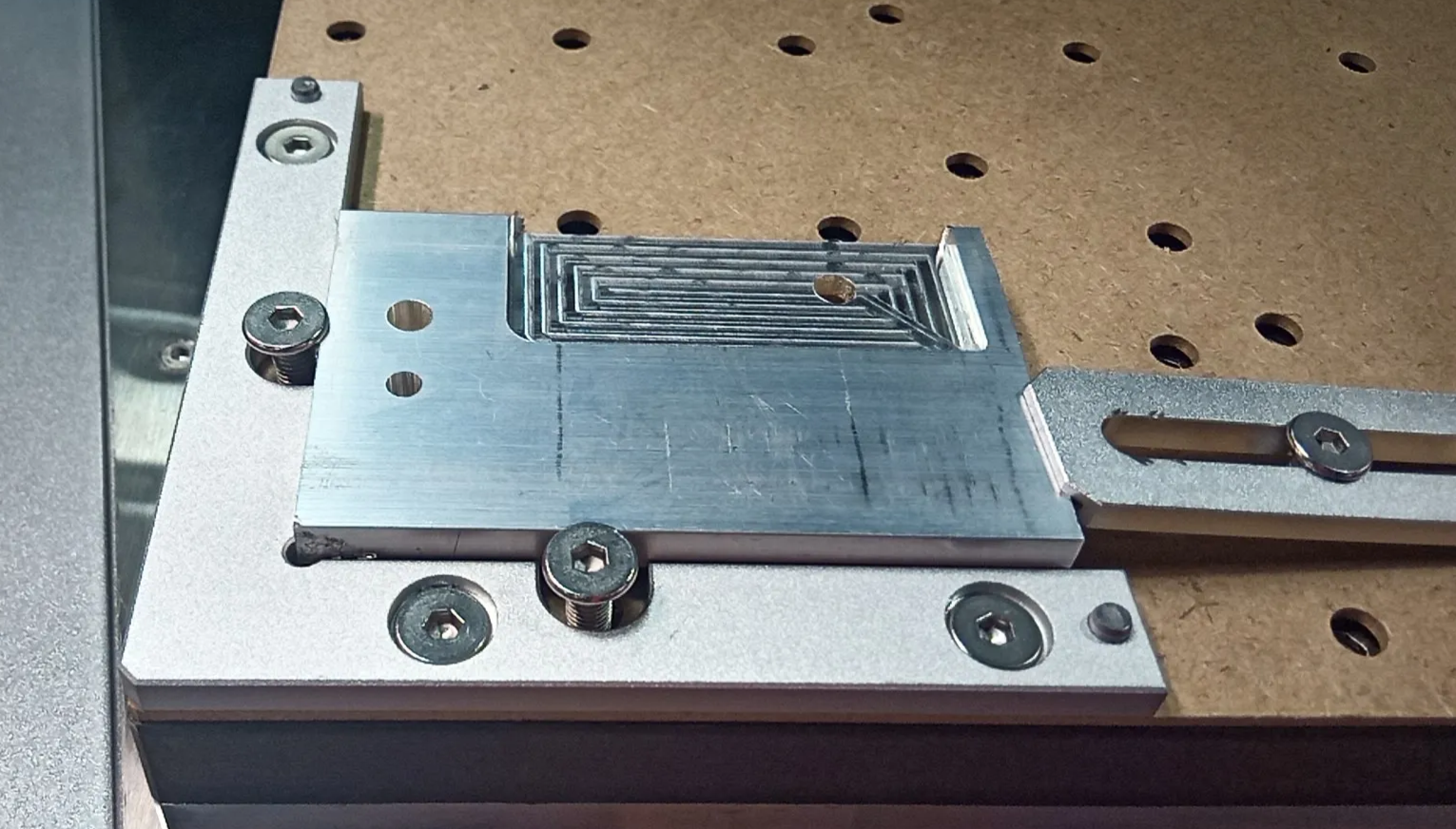
Setup 2 — Fixture Mounted
The part is bolted to the fixture plate through the holes bored in Setup 1. A sacrificial wasteboard sits between the part and the bed, protecting the machine's spoilboard during through-cuts.
// Part locked down to fixture plate via the previously bored holes. Sacrificial wasteboard visible between part and bed.
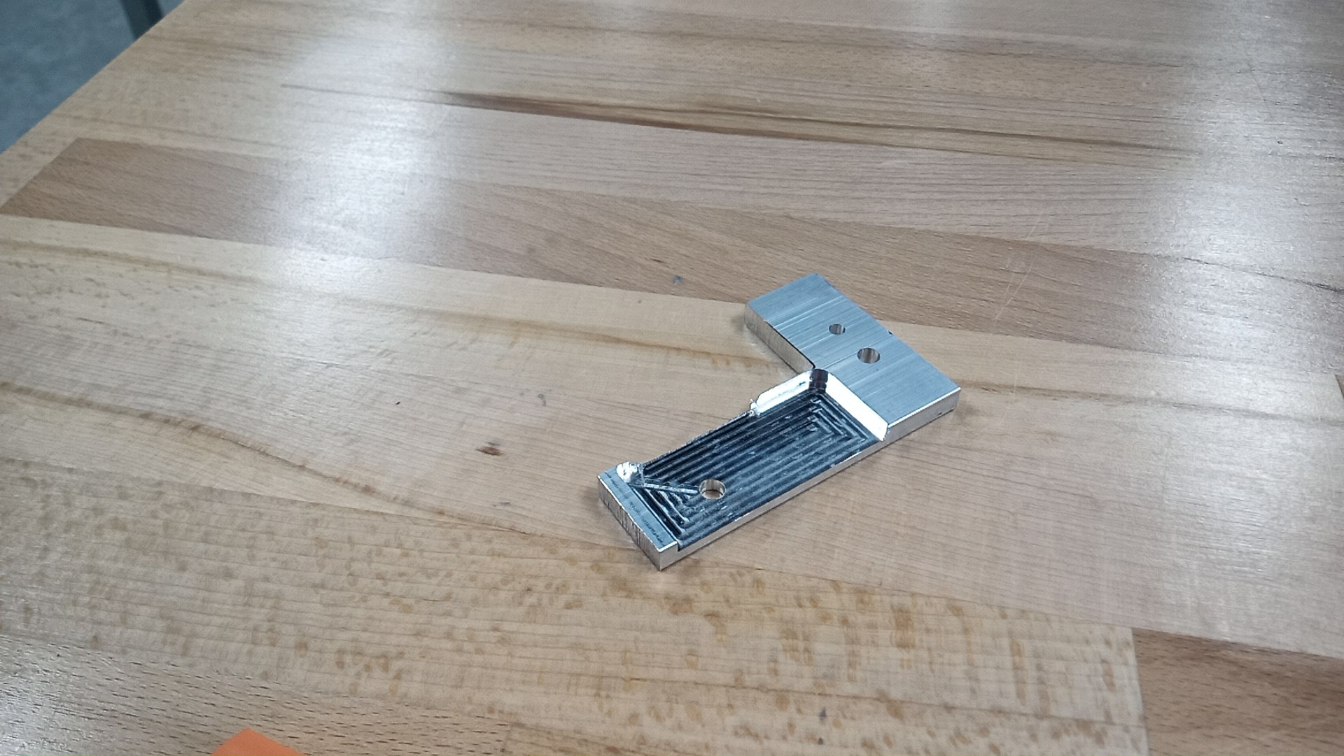
Op 4: Finalize the interior pocket — cutting the outer perimeter of the upper half of the part to final dimension.
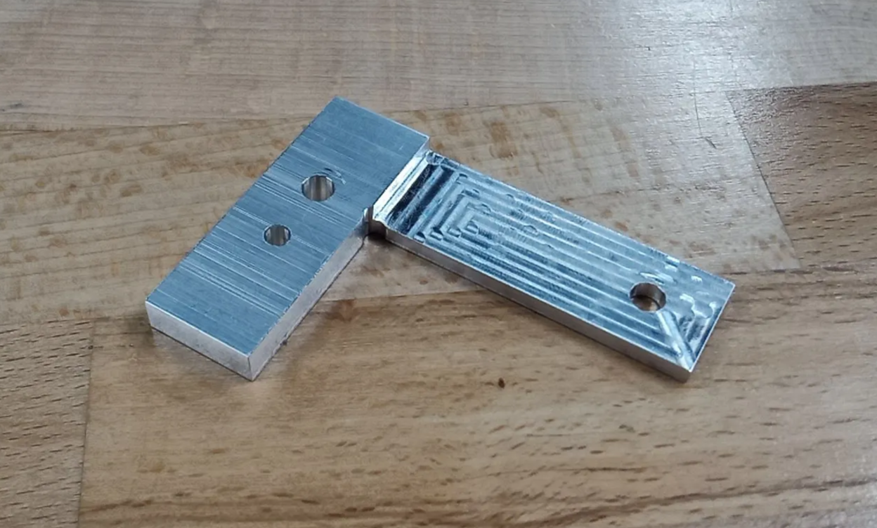
Op 5: Final contour — the full outer perimeter is cut in one continuous path, producing the four precision edges.
// Finished part after the final contour operation.
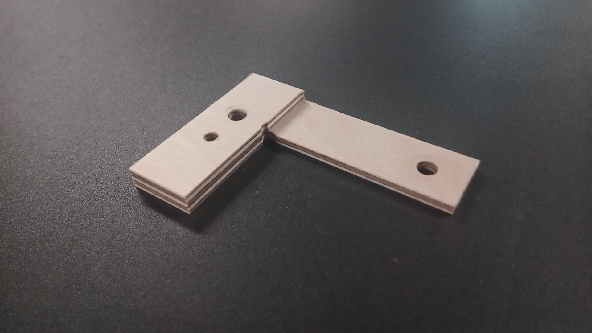
Bonus Note: Metal is expensive; plywood is cheap. A plywood sample was cut first to validate the G-code and check fit before committing to aluminium stock.
// Plywood test sample — G-code validated and fit confirmed before cutting metal.