Problem Statement
The goal was a tripod that could travel in any backpack, print on any consumer FDM printer (including compact machines like the Bambu A1 Mini), and accept standard camera accessories via a 1/4-20 threaded mount — all without requiring any purchased hardware beyond a single bolt.
| Max Height | ~6 inches (adjustable) |
| Thread Interface | 1/4-20 — industry standard for camera mounts |
| Portability | Fits in any backpack or large purse |
| Fabrication | Fully 3D printable, no supports required |
| Printer Compatibility | Sized for mini-format beds (e.g. Bambu A1 Mini) |
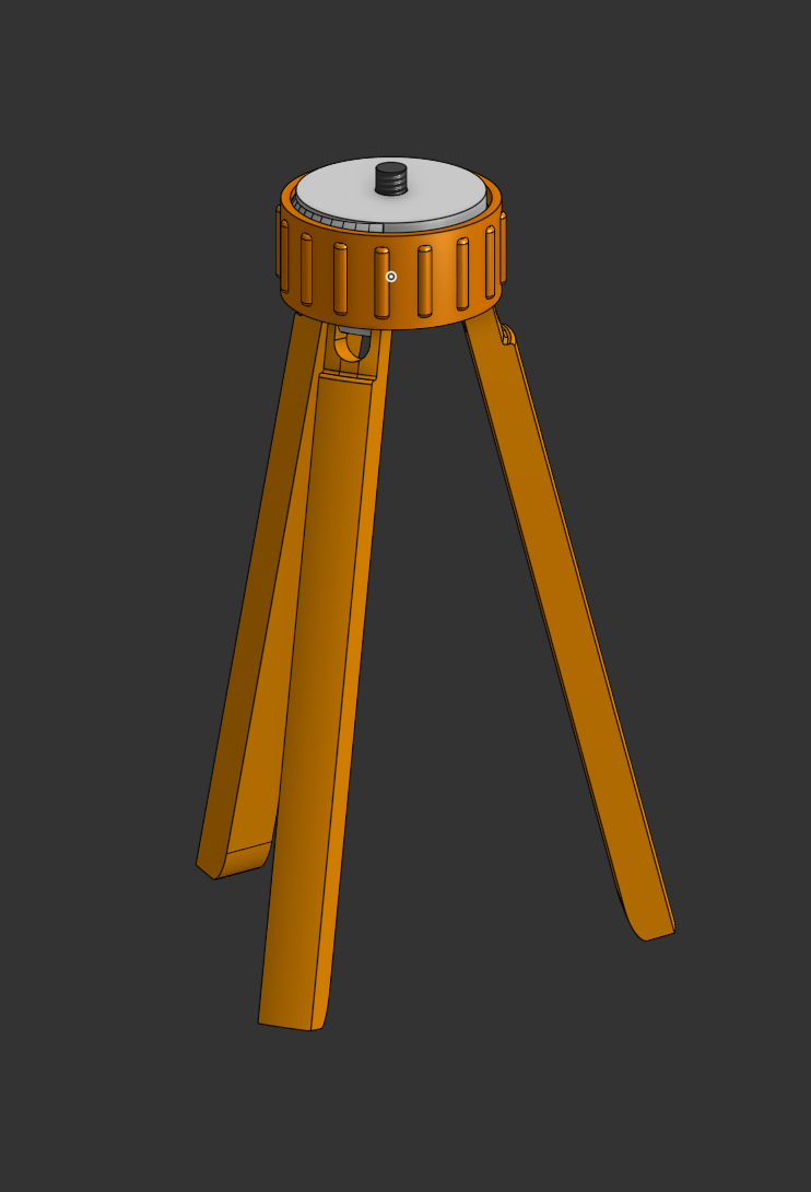
// Fully assembled tripod render. Ring (orange) rotates around the base (grey) to spread or retract the legs, adjusting height.
Design Concept: A threaded ring around the base pushes down on the legs as it turns, pulling them inward and lifting the platform. A magnet-retained 1/4-20 bolt spins freely in the top but won't fall out.
Sub-Project 1 — Stepped Threads
The central design challenge was height adjustment that holds position without a locking mechanism. Standard helical threads would allow the ring to rotate freely under any vibration. The solution: a stepped (ratchet-profile) thread that only engages in one rotational direction — allowing adjustment but resisting back-rotation.
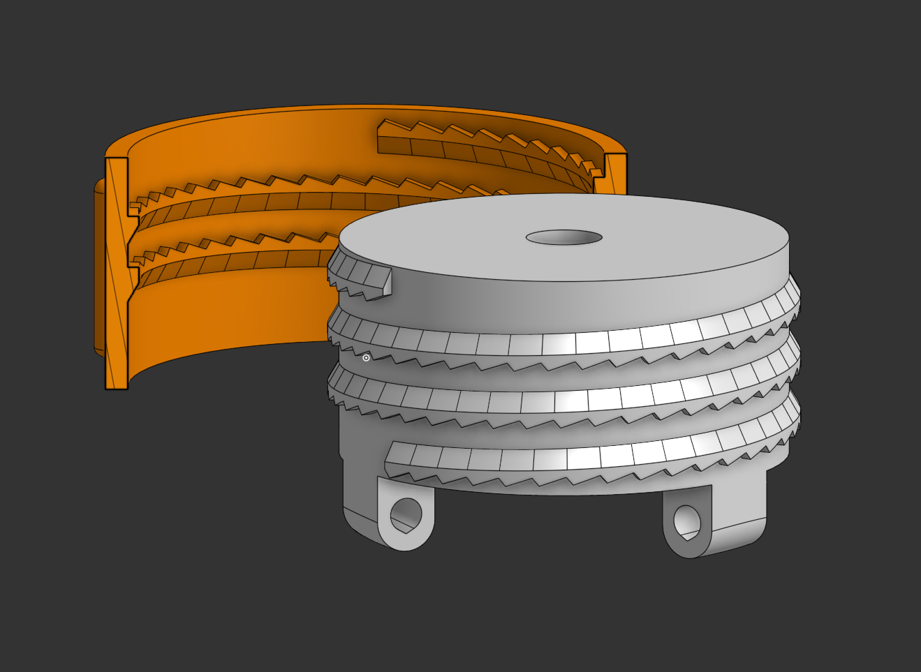
// Sectioned render showing the stepped tooth profile on both the base (grey) and the ring (orange). The asymmetric tooth geometry locks against reverse rotation.
CAD Methodology
- Model a base cylinder
- Create a helix around the surface of the cylinder
- Draw one "step" profile in a 2D sketch
- Project the helix onto the sketch to reference its geometry for alignment
- Apply a Wrap command, wrapping the step profile around the cylinder
- Pattern that step feature along the helix
- Chamfer the non-stepped edge — this makes the thread printable without supports
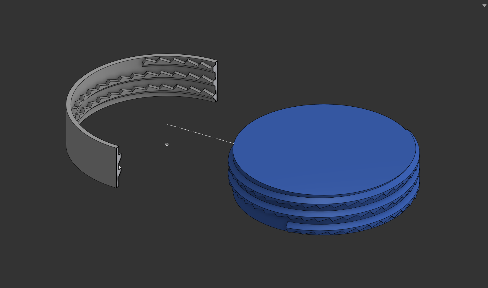
- Repeat with inverted geometry for the outer ring
- The step must be upside-down on the ring to mesh correctly with the base
// Modeled thread prototype. 3D printed to test the stepped geometry before integrating into the full design.
Sub-Project 2 — Snap Hinges
The legs needed to fold flat for transport and deploy reliably under (light) load. A snap-fit hinge was chosen over a bolted hinge to keep the design fully printable and make assembly easy. Several iterations were prototyped before landing on a geometry compact enough for the leg dimensions while still snapping positively into place.
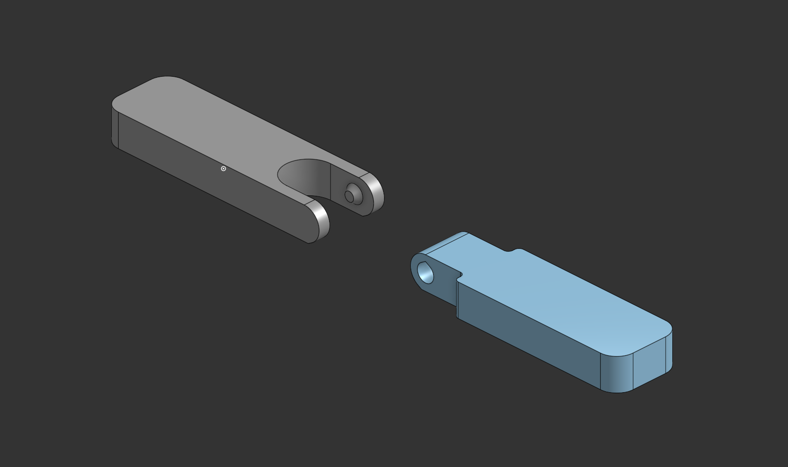
// Final snap hinge geometry after iterative prototype testing.
Documentation Note: A full technical drawing of the snap hinge was produced so the feature can be reproduced independently in any future project.
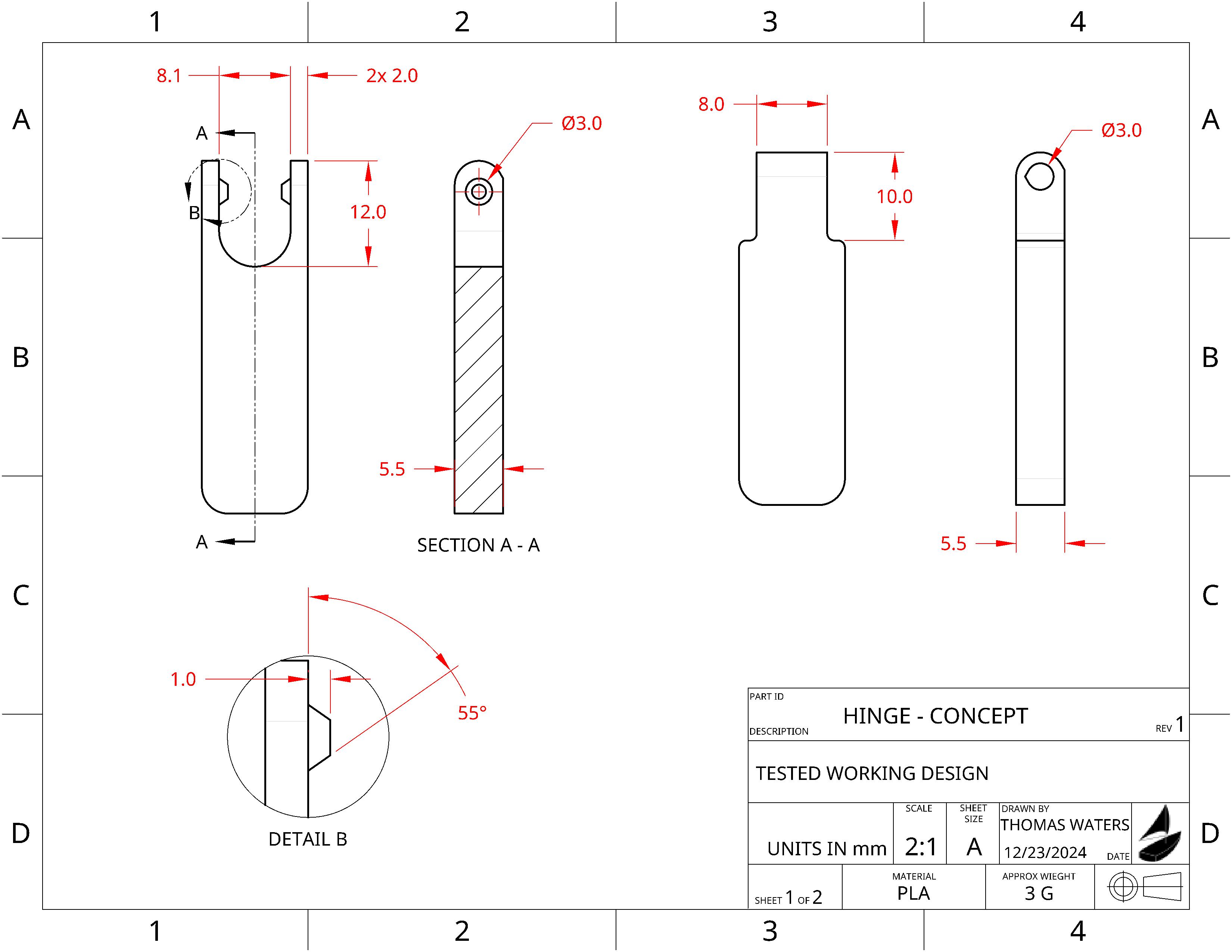
// Technical drawing of the snap hinge. Dimensions provided for direct re-use in other designs.
Sub-Project 3 — Magnet Retention
The 1/4-20 bolt at the top of the tripod needed to spin freely (so a camera mount can thread on without rotating the whole tripod) but must not fall out. The chosen solution: embed magnets in the base to retain a bolt with a permanently-installed free-spinning washer — found at a local hardware store as an automotive part.
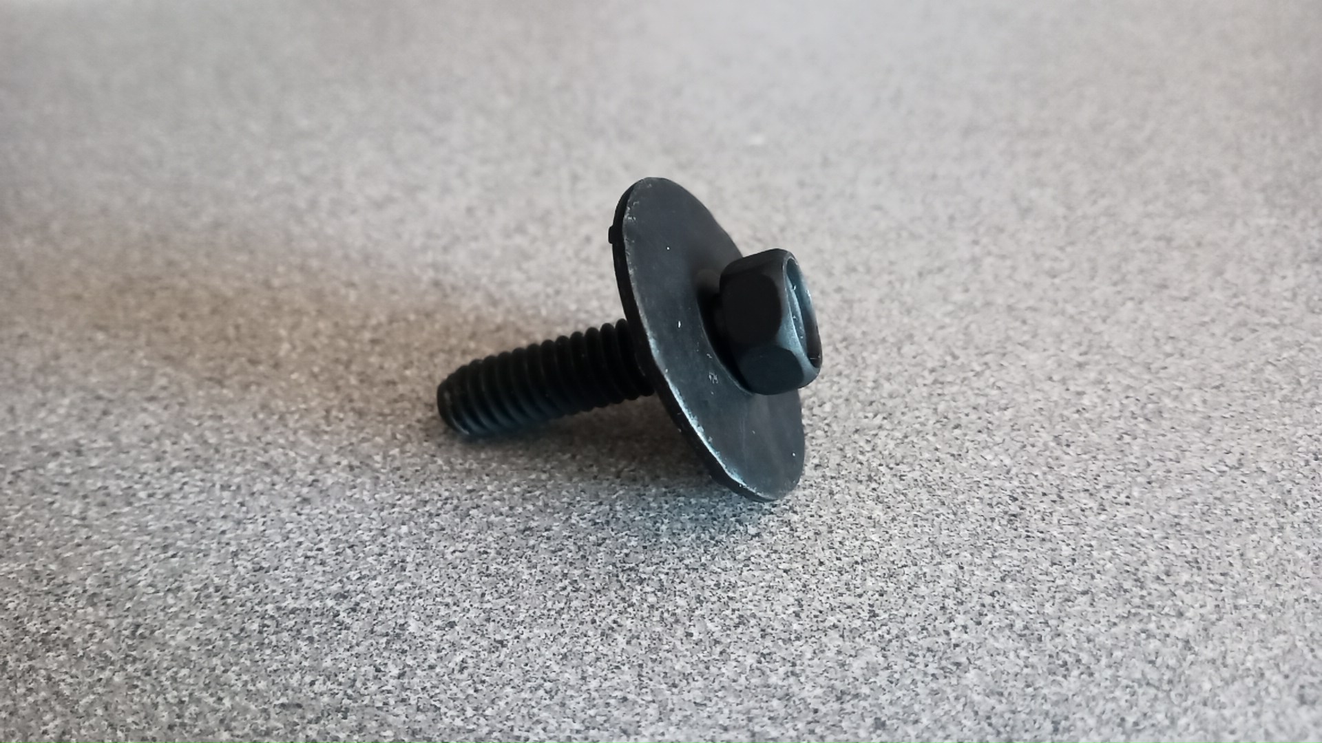
// The 1/4-20 bolt with a permanently-installed free-spinning washer — sourced from automotive hardware. The washer becomes the magnetic retention surface.
Experiment: How Many Magnets?
Rather than guess at the required magnet count, four variants were printed simultaneously — each holding a different number of magnets — and tested for pull strength before committing to the final design.
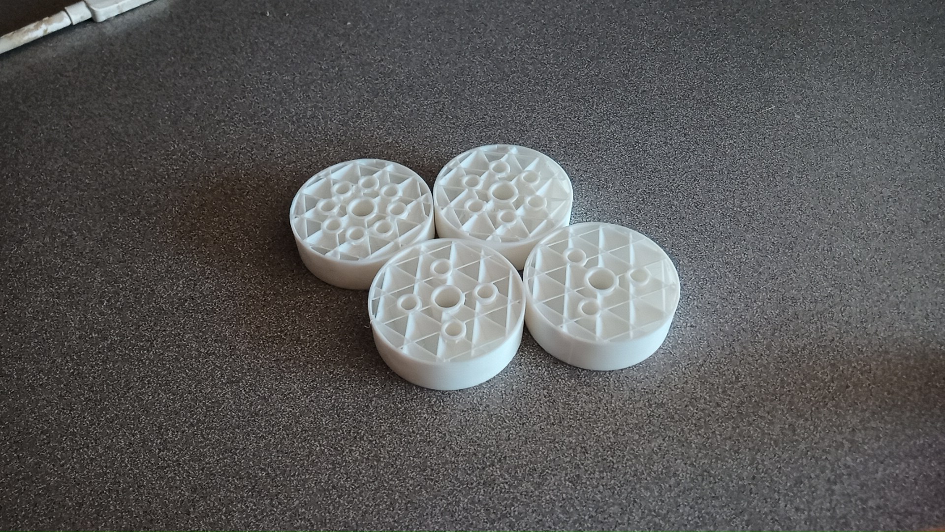
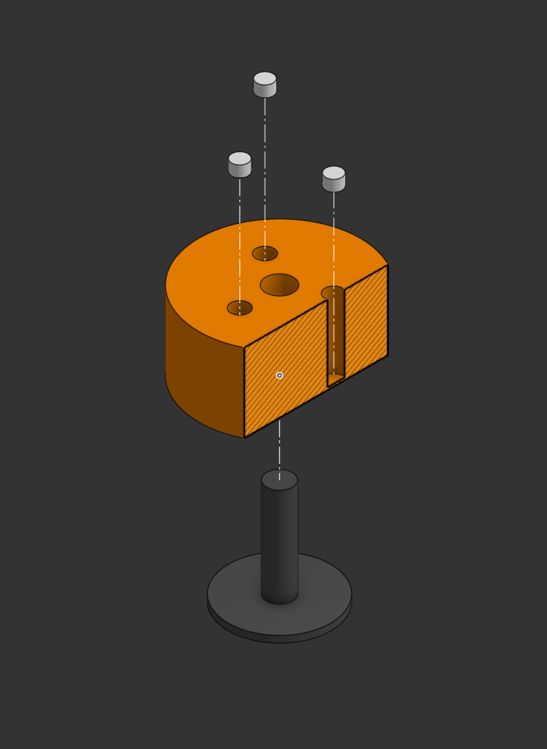
// Left: the four test prints with varying magnet counts. Right: CAD model of the magnet holder cavity geometry.
Result: Six magnets provided sufficient retention force. The magnet cavities are sized to allow ingress of three layers (0.6mm at standard quality), trapping the magnets permanently when printing resumes.
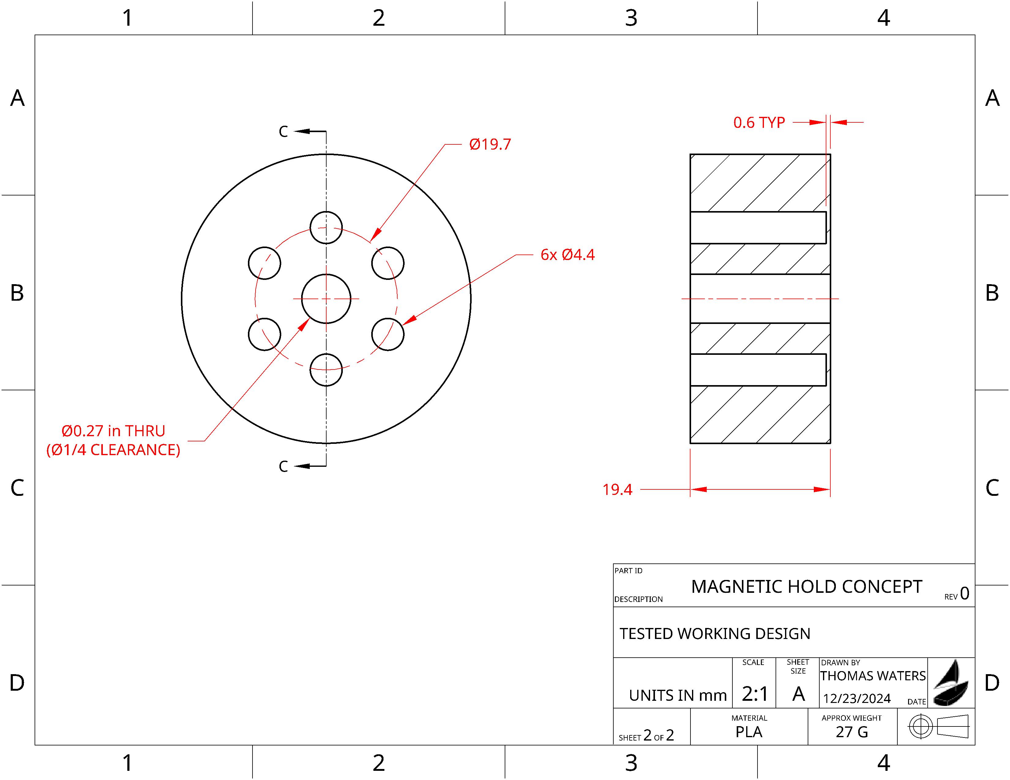
// Technical drawing of the magnet holder geometry — produced for reproducibility.
Final Assembly
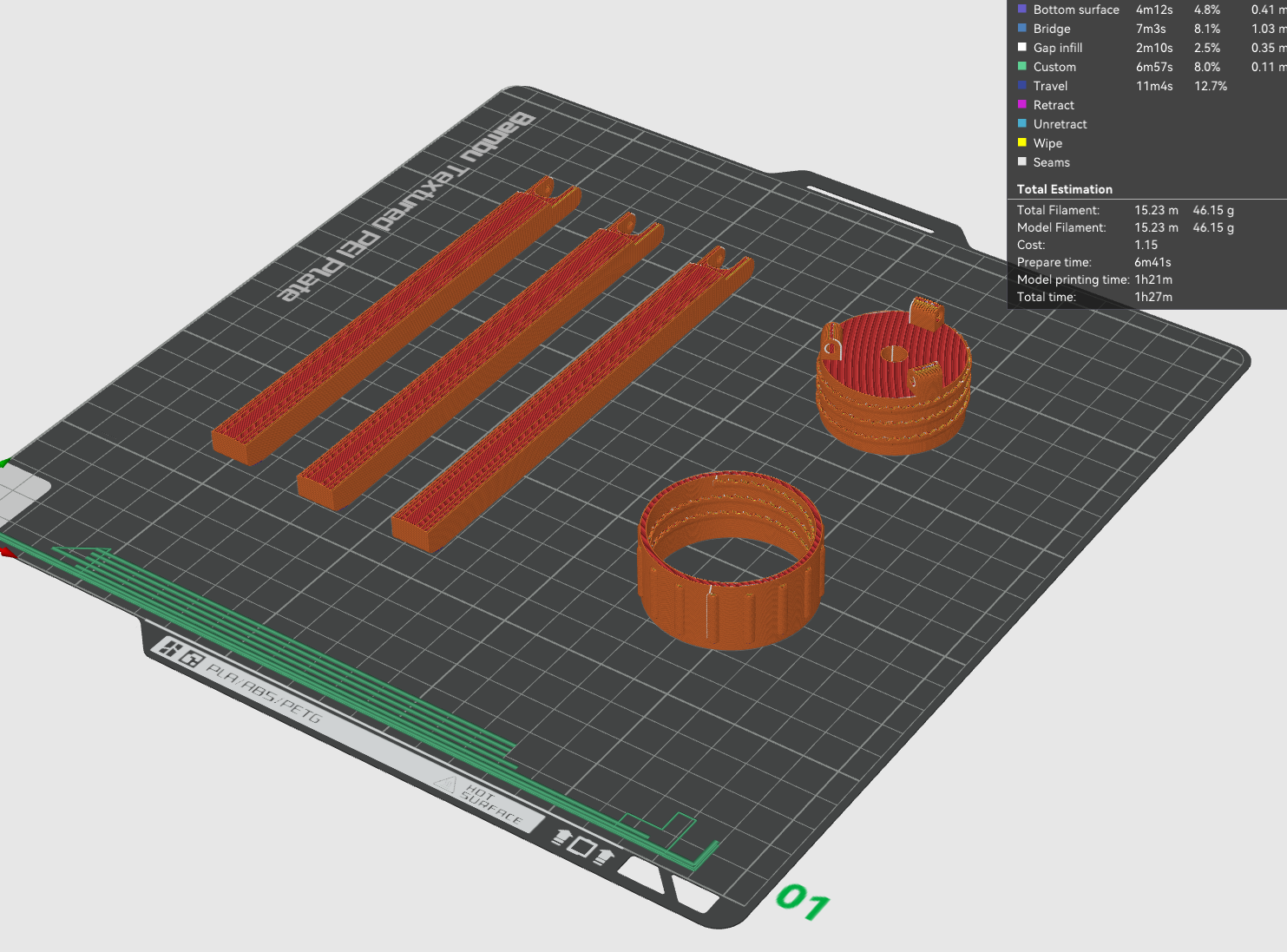
With all three sub-problems resolved — stepped threads prototyped, snap hinge geometry locked, magnet count confirmed — the full tripod was designed, printed, and assembled. The STEP files for all three components are published below for anyone who wants to print their own or adapt the design.
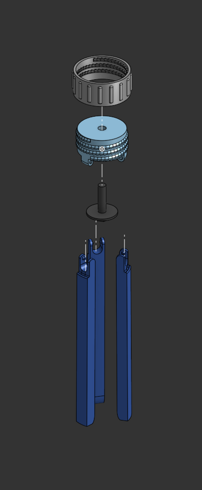
// Final CAD assembly views before printing.
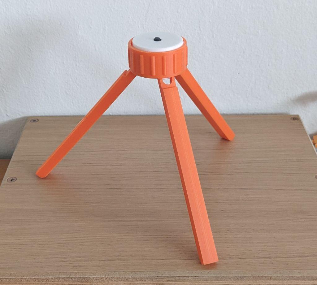
// The finished, assembled tripod.
Tip: The leg length can be customized using the "Move Face" command (or equivalent) in any CAD application — no rework of the thread or hinge geometry required.